1. Introduction
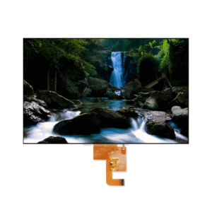
From the smartphone in your pocket to the industrial control panel on a factory floor, and from your car’s dashboard to a medical monitor in a hospital – TFT LCD displays are everywhere. They are the silent, reliable workhorses of the modern visual world.
But have you ever stopped to wonder: How does a flat glass panel convert faint electrical signals into vivid, high-definition moving images?
This article will take you on a deep technical dive into the inner workings of TFT LCD technology. By the end, you will not only understand its layered anatomy and step‑by‑step operation but also gain practical insights for selecting the right display for your next project.
2. What is a TFT LCD Display?
Deconstructing the Acronym
- TFT – Thin Film Transistor
- LCD – Liquid Crystal Display
The Core Concept
TFT refers to an active matrix technology. Unlike older passive matrix displays, where rows and columns shared control lines, a TFT LCD assigns a dedicated miniature transistor to each individual pixel (or sub‑pixel) on the screen. This allows every pixel to be switched on or off independently, with no crosstalk between neighbors.
Key Competitive Advantages
- High resolution – millions of independently controlled pixels
- Fast response time – essential for video and dynamic content
- Excellent contrast and color accuracy – thanks to precise voltage control
3. Anatomy of a TFT LCD – The Key Components
To understand how a TFT LCD works, you must first visualize its “sandwich” structure, built layer by layer from back to front:
| Layer | Function |
|---|---|
| Backlight Unit (BLU) | High‑brightness LEDs provide the light source. LCDs do not emit light by themselves. |
| Rear Polarizing Filter | Converts natural light into vertically polarized light. |
| TFT Glass Substrate | Contains millions of thin‑film transistors acting as individual electronic switches. |
| Liquid Crystal Layer | The “magic” material – its molecules twist or untwist when an electric field is applied. |
| Color Filter Layer | RGB (red, green, blue) sub‑pixel grid that creates full color. |
| Front Polarizing Filter | Oriented perpendicular (90°) to the rear filter. |
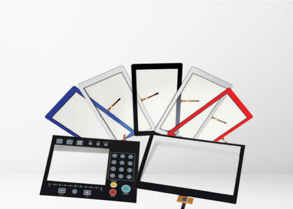
| Front Glass / Touch Panel | Protective outer layer and interactive surface. |
4. Step‑by‑Step: How a TFT LCD Display Works
This section is the technical heart of the article. Each step acts like a precision‑engineered gate for light.
Step 1 – Light Generation & Initial Polarization
The LED backlight emits white, unpolarized light (waves vibrating in all directions). As this light passes through the rear polarizing filter, only waves vibrating in a specific direction (e.g., vertical) are allowed through. The result: vertically polarized light entering the liquid crystal layer.
Step 2 – The Electrical Trigger
The display driver sends a precise voltage signal to the TFT transistor of a target pixel. The transistor instantly switches on, creating a local electric field between two transparent electrodes that sandwich the liquid crystal layer.
Step 3 – The Liquid Crystal “Light Gate”
- No voltage (field off):
Liquid crystal molecules naturally form a 90° twisted spiral. The vertically polarized light follows this twist and exits the layer rotated by 90° – now horizontally polarized. It perfectly aligns with the front polarizing filter (which is horizontal) and passes through. Pixel appears white / bright. - Voltage applied (field on):
Liquid crystal molecules straighten upright, losing their twisting ability. The vertically polarized light passes through without rotation. It reaches the horizontal front polarizer and is completely blocked. Pixel appears black / dark.
By applying intermediate voltages, the crystals partially twist, allowing some light through – creating shades of gray.
Step 4 – Color Mixing
Each pixel on a TFT LCD is actually three sub‑pixels: red, green, and blue (RGB). The TFT independently controls the brightness (grayscale) of each sub‑pixel. These three tiny colored patches blend optically at a distance, producing millions of colors.
Example: Full red = red sub‑pixel fully on, green and blue off. Yellow = red and green on, blue off.
5. Why TFT? Active Matrix vs. Passive Matrix
Before TFT, passive matrix LCDs (e.g., STN) were common. How did they work? Rows and columns shared control lines. This led to:
- Slow response – noticeable motion blur / ghosting
- Crosstalk – activating one pixel accidentally affected its neighbors
- Poor contrast
The TFT revolution:
Every sub‑pixel has its own transistor that holds charge between refresh cycles. This eliminates crosstalk, delivers sub‑millisecond response times, and enables high‑resolution video and sharp static images alike.
6. TFT LCD vs. OLED – A Quick Tech Comparison
This comparison not only captures search traffic for “TFT vs OLED” but also highlights why TFT remains the #1 choice for industrial and embedded applications.
| Feature | TFT LCD | OLED |
|---|---|---|
| Light source | Passive backlight (LED) | Self‑emissive organic material |
| True black level | Very good, but backlight always on | Pixels turn completely off – infinite contrast |
| Brightness in sunlight | Excellent – high luminance possible | Moderate, risk of burn‑in |
| Burn‑in risk | None | Yes – static images leave permanent marks |
| Operating temperature | Wide range (-30°C to +85°C) | Narrower (0°C to +70°C typical) |
| Lifespan | >50,000 hours, very stable | Shorter, especially blue sub‑pixels |
Conclusion for engineers: For medical devices, automotive dashboards, industrial HMIs, and any application requiring reliability, longevity, and readability in harsh environments – TFT LCD is the proven winner.
7. Conclusion & Commercial Call‑to‑Action
The seemingly simple image on a TFT LCD screen is the result of a beautiful synergy: the precise switching power of thin‑film transistors combined with the optical flexibility of liquid crystals. Understanding this technology goes beyond academic curiosity – it directly impacts your display selection process: brightness, viewing angle, operating temperature, and interface requirements.
Looking for a reliable TFT LCD partner?
Whether you need a standard display or a fully customized module for your industrial control system, automotive cluster, or embedded project, our engineering team is here to help. We provide high‑reliability TFT LCD solutions tailored to your technical specifications.
👉 Contact us today at Jictech / jicdisplay.com for a no‑obligation consultation and a custom quote.
FAQ – Frequently Asked Questions
Q1: Is TFT LCD the same as IPS?
No. IPS (In‑Plane Switching) is a specific type of TFT LCD technology that offers wider viewing angles and better color reproduction compared to standard TN (Twisted Nematic) TFTs.
Q2: Do TFT LCDs consume more power than OLEDs?
Not necessarily. For mixed content (white backgrounds), TFT LCDs can be efficient. OLEDs consume less power when displaying mostly dark content but more for bright, full‑screen white.
Q3: Can TFT LCD displays work in freezing temperatures?
Yes. Many industrial TFT LCDs are rated for -30°C or even lower with optional heaters. OLEDs generally struggle below 0°C.
Q4: What is the lifetime of a TFT LCD backlight?
Typical LED backlights in TFT LCDs are rated for 50,000 to 100,000 hours (about 5.7 to 11+ years of continuous use).
Q5: Why does my TFT LCD look dark from an angle?
That is typical for TN (Twisted Nematic) TFT panels. For wider viewing angles, choose IPS or VA TFT LCD modules.